Procedure
24/04/2024
WiFi Controlled LED
Components required:
- Knewton board – 1
- Arduino Nano Cable – 1
- Bright LED – 1
- Power Bank-1
- USB to DC jack-1
- ESP WiFi module – 1
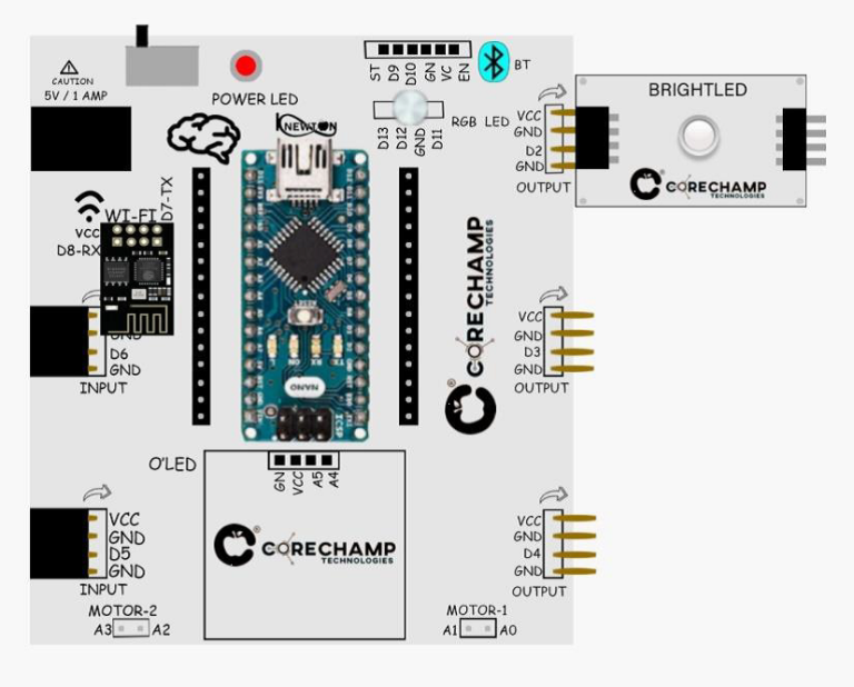
Circuit Diagram:
- Arrange the circuit as shown in
the image. - Connect Wifi Module In allotted
connection space. - Connect Bright LED in D2 of board .

Arduino Code:
Process 1 – Changing Baud Rate of ESP WiFi module
- Make sure your giving supply to board through DC power input of board.
- Now open the Arduino IDE and upload the code given in QR-1.
- Now open serial monitor and use the given AT command
AT+UART_DEF=9600,8,1,0,0
- You will see OK printed only once.
- Next, we’ll have to install the RemoteXY libraries in Arduino IDE.
- Scan the QR-2 to download the zip files of RemoteXY Library.
Code:
//Changing the Baudrate
#include <SoftwareSerial.h>
SoftwareSerial SerialM(7,8);
void setup() {
Serial.begin(115200);
SerialM.begin(115200);
delay(2000);
}
void loop() {
while (SerialM.available() > 0) {
Serial.write(SerialM.read());
}
while (Serial.available() > 0) {
SerialM.write(Serial.read());
}
}


- Once libraries are installed, copy the code on QR-3 and paste it in your Arduino IDE.
- Change the WiFi name (SSID) and password of your WiFi in the code.
- Now upload the code.
Code:
//WiFi controlled LED
#define REMOTEXY_MODE_ESP8266_SOFTSERIAL_CLOUD
#include <SoftwareSerial.h>
#include <RemoteXY.h>
// RemoteXY connection settings
#define REMOTEXY_SERIAL_RX 7
#define REMOTEXY_SERIAL_TX 8
#define REMOTEXY_SERIAL_SPEED 9600
#define REMOTEXY_WIFI_SSID “YOUR_SSID” //Replace with the SSID of your WiFi
#define REMOTEXY_WIFI_PASSWORD “YOUR_PASS” //Change with the passsword of your WiFi
#define REMOTEXY_CLOUD_SERVER “cloud.remotexy.com”
#define REMOTEXY_CLOUD_PORT 6376
#define REMOTEXY_CLOUD_TOKEN “694a3cf7fa1ebf247f109db8801d856a” //This is the Auth token
// RemoteXY configurate
#pragma pack(push, 1)
uint8_t RemoteXY_CONF[] =
{ 255,1,0,0,0,13,0,15,31,1,
1,0,22,20,12,12,2,31,88,0 };
// this structure defines all the variables and events of your control interface
struct {
// input variables
uint8_t button_1; // =1 if button pressed, else =0
// other variable
uint8_t connect_flag; // =1 if wire connected, else =0
} RemoteXY;
#pragma pack(pop)
/////////////////////////////////////////////
// END RemoteXY include //
/////////////////////////////////////////////
#define PIN_BUTTON_1 13
void setup()
{
RemoteXY_Init ();
pinMode (PIN_BUTTON_1, OUTPUT);
// TODO you setup code
}
void loop()
{
RemoteXY_Handler ();
digitalWrite(PIN_BUTTON_1, (RemoteXY.button_1==0)?LOW:HIGH);
// TODO you loop code
// use the RemoteXY structure for data transfer
// do not call delay()
}

Output:
- Once the code is uploaded, we’ll install the RemoteXY app from the Google Playstore. Connect to cloud server using
Device token:- 694a3cf7fa1ebf247f109db8801d856a
Port:-6375
- You will be able to control the led using Wi-Fi and phone.
