Back to Course
PCB Designing
0% Complete
0/0 Steps
-
INTRODUCTION4 Topics
-
CONDUCTOR AND CONDUCTIVE PATHS3 Topics
-
ZERO PCB
-
OVERVIEW OF ELECTRONICS4 Topics
-
What do you mean by Electronics??
-
What Do you mean by Electronic Components??
-
Some Basic Electronic Components and their symbols
-
Types of Electronic Components according to their assembly
-
What do you mean by Electronics??
-
ACTIVITY 11 Quiz
-
CLASSIFICATION OF PCB2 Topics
-
COMPOSITION OF PRINTED CIRCUIT BOARD3 Topics
-
BRIEF ABOUT COPPER
-
COLOR OF THE PRINTED CIRCUIT BOARD
-
ACTIVITY 21 Quiz
-
PCB DESIGNING2 Topics
-
PCB DESIGNING SOFTWARE3 Topics
-
ACTIVITY 31 Quiz
-
EAGLE OVERVIEW2 Topics
-
WHAT IS EAGLE
-
EAGLE PLATFORM
-
WHAT IS EAGLE
-
PCB TERMINOLOGIES13 Topics
-
ACTIVITY 41 Quiz
-
SCHEMATIC STUDY4 Topics
-
ACTIVITY 51 Quiz
-
SCHEMATIC DESIGN13 Topics
-
ASSIGNMENT 12 Topics
-
ACTIVITY 61 Quiz
-
LAYOUT DESIGN8 Topics
-
Activity 71 Quiz
-
ROUTING5 Topics
-
ASSIGNMENT 21 Topic
-
ROUTING RULES6 Topics
-
ERC8 Topics
-
DRC3 Topics
-
ACTIVITY 81 Quiz
-
GROUND PLANE
-
GERBER GENERATION4 Topics
-
BILL OF MATERIAL1 Topic
-
ACTIVITY 91 Quiz
-
PCB MANUFACTURING
-
MISCELLANEOUS ACTIVITY1 Quiz
-
MISCLLANEOUS ASSIGNMENT1 Topic
Lesson 37 of 36
In Progress
LIBRARY
02/02/2023
A PCB library contains one or more PCB footprints that represent the physical pad arrangement and other mechanical attributes of the component.
EAGLE CAD has libraries for each family of devices like passive components (rcl.lbr), diodes (diode.lbr), transistors (transistor.lbr), power supplies (supply.lbr) and so on.
To use a certain library in a project you should first say tot the program to use that library. This is accomplished in the schematic editor by selecting the Use option from the Library menu. A selection window appear, that allows you to chose the libraries you want to include/use in the project.
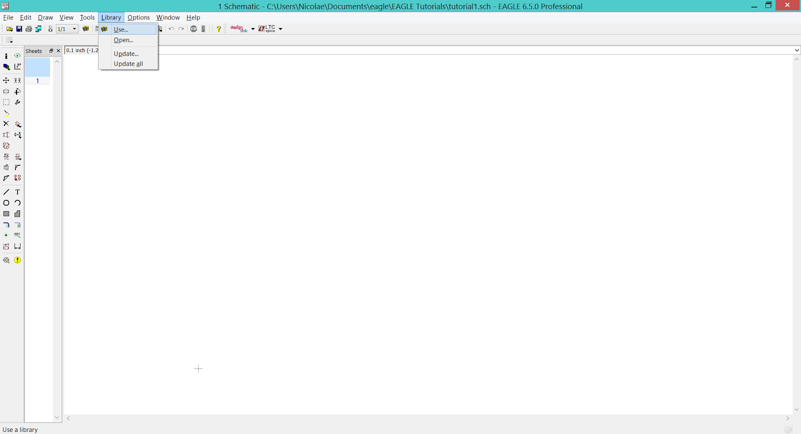 |
| EAGLE CAD – How to add a library to the project |
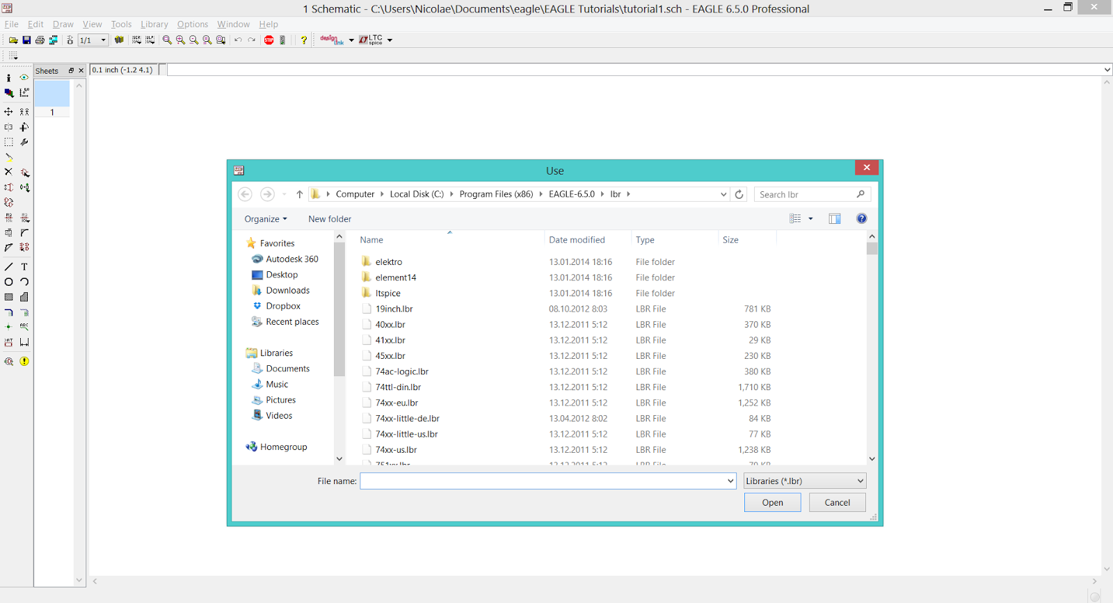 |
| EAGLE CAD – Use Library Window |
Once included, the library can be accessed with the tool Add from the tool panel. Using this tool opens a window that contains all the libraries that are in use.
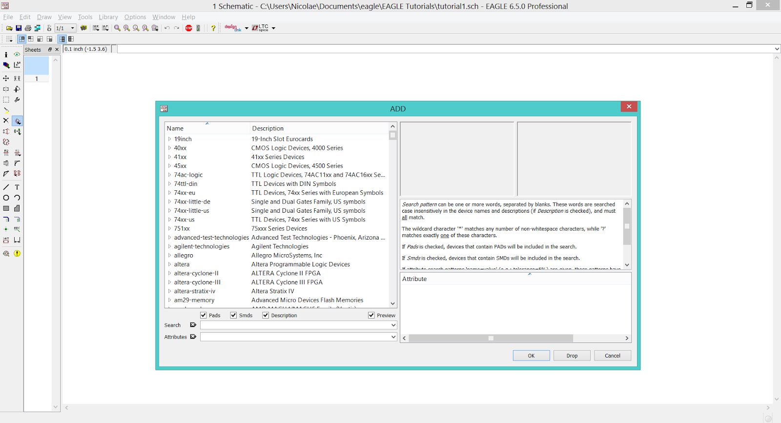 |
| EAGLE CAD – Add window |
If you want to place a resistor on your schematic you should go to the rcl.lbr library and select the appropriate type for your project:
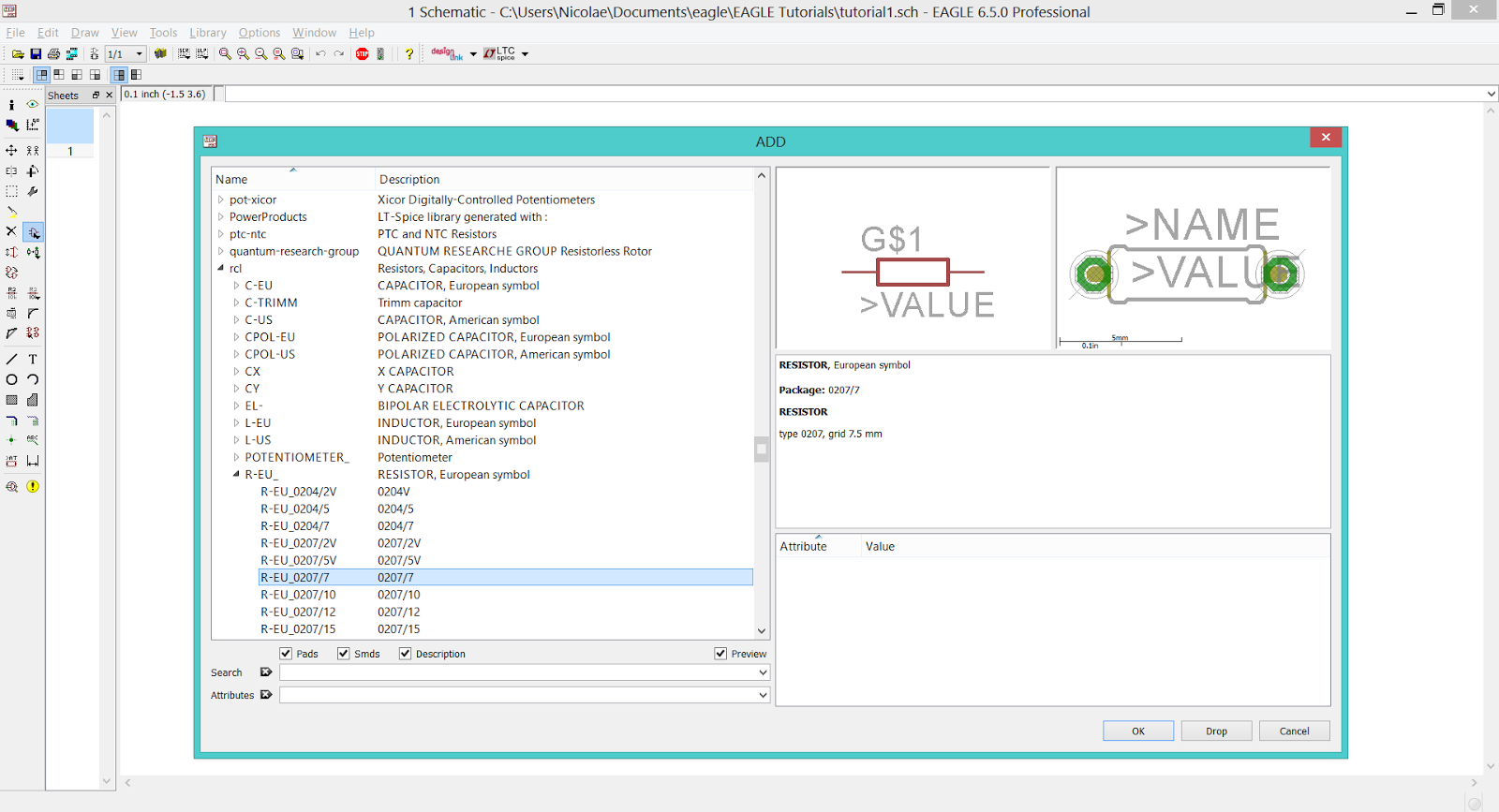 |
| EAGLE CAD – Adding a resistor to the schematic |
On the left side of the Add window I selected the rcl.lbr library which expanded. From the expanded list I selected the R-EU option which expanded as well, allowing me to see all available types of resistors.
The left column contains the resistors names and the right column contains the name of the package (footprint). The selected resistor is named R-EU_0207/7 and it’s package is a 0207/7 (THT resistor).
The right side of the Add window contains images of the symbol and package, as well as additional data about the selected component.
To use the selected device into schematic simply press the OK button (right side, bottom) and you will be allowed to place the device wherever you want on the workspace by left-clicking. You can place how many components you like, until you press the ESC button.
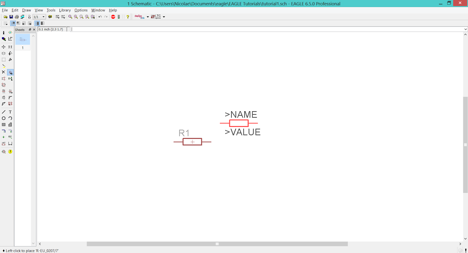 |
| EAGLE CAD – Adding a resistor to the schematic |
Commonly used libraries:
- Power Supply – supply1.lbr, supply2.lbr
- Pin Headers – con-lsta.lbr, con-lstb.lbr
- Screw Connectors – con-ptr500.lbr
- Resistors (european symbol) – rcl.lbr > R-EU_ (for US symbols replace EU with US)
- Capacitors (european symbol) – rcl.lbr > C-EU
- Polarized Capacitors (european symbol) – rcl.lbr > CPOL-EU
- Inductors (european symbol) – rcl.lbr > L-EU
- Diodes – diode.lbr
- NPN Transistors – transistor-npn.lbr
- PNP Transistors – transistor-pnp.lbr
- Field Effect Transistor – transistor-fet.lbr
- LED’s – led.lbr > led
- Voltage Regulators – v-reg.lbr